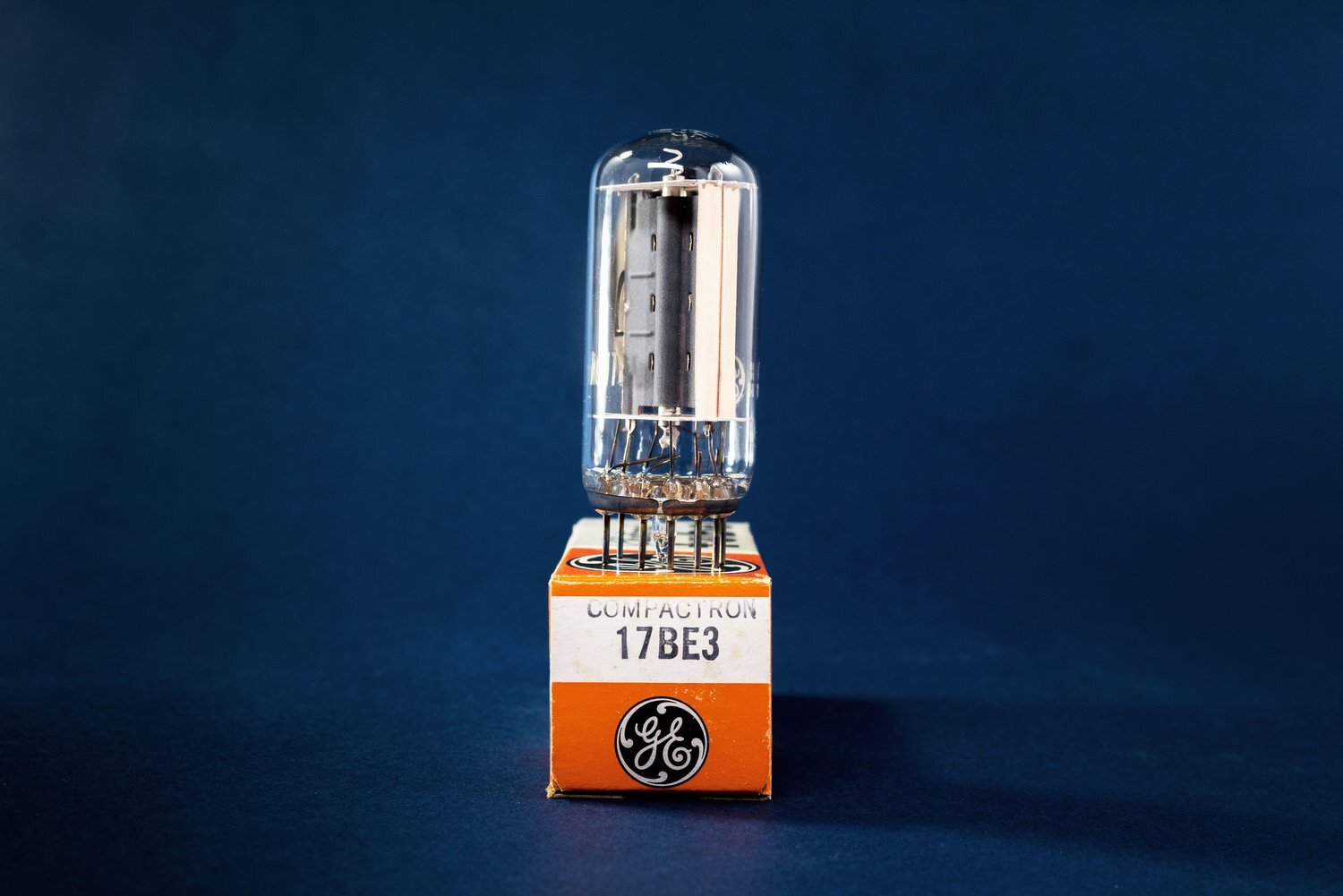
How Vacuum Tubes Work

All tubes follow the same basic principles. Inside a tube’s glass enclosure, you have 1) a vacuum and 2) at least two electrodes (but often more, depending on what type of tube we’re talking about). Each electrode has a specific job: either releasing electrons, attracting electrons, or slowing down or speeding up the flow of electrons. We’ll talk about these jobs later. For now, the main thing that tubes are intended for is to direct electrical current from A to B in some way that is useful to the circuit.
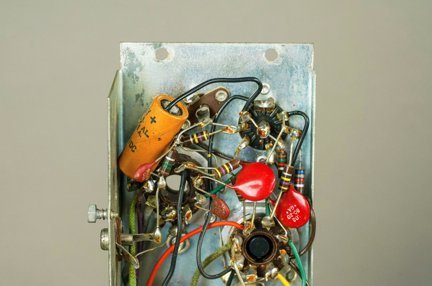
The electrodes are able to perform their jobs because all of the tube’s electrodes are enclosed in a vacuum. Hence the “vacuum” part of vacuum tubes: during the tube’s manufacture, the air is removed from the inside of the glass envelope. The evidence of the tube’s vacuum is the silver metallic coating on the inside, which is called the getter. Getter helps maintain the vacuum by removing residual gases that are released by the materials inside the tube.
In a vacuum, electricity can travel just as easily as it does through a wire. If the tube loses its vacuum, the electrons no longer have a clear path from electrode to electrode, and the tube stops working. The getter is an indication of a healthy vacuum. As long as the getter is shiny, the vacuum is good. If the getter turns white, air has leaked into the envelope and compromised the vacuum.
Note that, in many ways, thinking about electricity requires thinking in metaphor. Electricity does not behave in any way that is easy to conceptualize. For instance, we talk about electron “flow,” but electrons don’t flow in the same way as, for instance, water flows. Individual electrons move randomly in the general direction of the current, but circuits don’t require every single electron to physically fly through a wire (or, for that matter, a vacuum) like so many billiard balls. The important thing isn’t the literal motion of single electrons; it is the general directions that the group of electrons is trending towards. Electrons don’t flow like a rushing river; their flow is more like that a single drop of water on a flat surface, vibrating in a gust of wind.
So, although we are trying for accuracy, any non-mathematical description of how circuits work is necessarily simplified.
Diodes: the first tube type
How does a diode work? A diode is the simplest and earliest form of vacuum tubes. It has two electrodes: an anode (i.e., the plate) and a cathode. When the cathode is hot, its electrons get excited. Hot, excited electrons have the ability to fly off the cathode into the vacuum. If the plate is more positive than the cathode, these electrons will be attracted towards it and a current will flow through the tube.
So, electrons flow from the hot cathode to the plate. However, electrons won’t make the reverse trip — from the plate to the cathode — because, first of all, the plate isn’t hot (so the plate’s electrons aren’t excited) and also because the cathode is more negative than the plate (so the electrons don’t find it particularly attractive). A diode is strictly a one-way street.

A diode also cannot amplify signals. However, because current only moves through a diode in one direction, a diode can be used to convert alternating current into direct current. This is called rectification. In its simplest form, a rectifier diode allows half of an AC waveform to pass and blocks the other half.
Common tube diodes. Diodes have various applications, but today, tube diodes are almost exclusively used to rectify AC line voltage into DC power supply voltage. DC voltage is more appropriate for powering the plates of preamp and power amp tubes, and tube rectifiers give power supplies a particular vintage character. For all other applications, tiny silicon diodes are used instead. Common tube diodes include the 5Y3, 5U4, 5AR4, 6CA4, and GZ34.
How does the cathode get hot? Usually, the cathode is heated via a separate electrode called the filament (also known as the heater). The filament is composed of a heat-resistant metal, usually tungsten, which is positioned close to the cathode. A current is applied to the filament, causing it to heat up to a temperature of around 1000º F. This hot filament is what gives tubes their characteristic glow. However, in some tubes, the cathode and the filament are one and the same. These tubes have directly-heated cathodes, in contrast to tubes with indirectly-heated cathodes.
Most tubes use indirectly-heated cathodes. This is because the heaters are typically powered with noisy AC. If the cathodes were directly heated, this noisy AC would introduce a lot of hum into the signal. As it is, it is very easy for heater noise to leak into the cathode, just because these electrodes are by necessity positioned very closely together. It is also easy for heater noise to leak into the circuit generally, because heater currents tend to be relatively large. Anyway, heaters are a necessary evil, and an indirectly-heated cathode is a good compromise between increased noise and the tube’s basic functionality.
However, directly-heated cathodes are still found in some tube types: mostly rectifiers. Directly-heated cathodes are acceptable in a rectifier because the heater voltage is very small: certainly no larger than the DC ripple which is the inevitable result of rectification. That DC ripple should be filtered out before it reaches any sensitive gain stages, and the filtering process will also remove any heater noise that enters through the rectifier tube.
Triodes: the first amplifiers
How does a triode work? Diodes are useful, but they’re something of a one-trick pony. They can really only rectify. A tube that amplifies, on the other hand, can be used in any number of applications. So how can a tube be made to amplify?
To amplify, a tube must have a third electrode (really, a fourth, if we’re counting the filament — but we’re not, because, if we did, the name “triode” doesn’t make sense anymore). This electrode is called the grid, and it is positioned between the cathode and the plate.
The polarity of the grid — i.e., whether it has a positive or negative charge — determines how appealing it is to hot cathode electrons. If the grid is positive, cathode electrons really want to head towards it. But if the grid is negative, electrons are repelled.
You can manipulate the behavior of these electrons by applying a signal voltage to the grid — for instance, using a guitar. For simplicity, you can imagine a guitar’s voltage as a sine wave (although in reality it is much more complex, thanks to the instrument’s harmonics): that is, an alternating current that periodically switches between a positive and negative polarity. When a tube cathode sees this current on the grid, electrons will flow from the cathode to the plate in a manner that corresponds with the behavior of the guitar signal. This means more electrons move towards the plate when the signal is positive, and fewer electrons do so when the signal is negative. For this reason, the output signal will be 180 degrees out of phase with the input.
Also, this electron flow from cathode to plate is much larger than the input signal voltage on the grid. In other words, the output voltage is amplified. This is because the input signal’s role is to modulate the flow of electrons; the strength of the input signal has an influence but does not dictate the strength of the output. Rather, output voltage swing is determined by the size of the plate resistor and the triode’s overall bias.
So, the signal applied to the grid of a triode appears on the plate, with three changes:
The new signal will be out of phase (i.e., flipped 180 degrees)
The new signal will be amplified
The new signal will have additional new harmonics due to irregularities in the tube (this is perceived as appealing tube warmth)
Distortion. You can bias a triode so that the output is a faithful (but louder and out-of-phase) version of the input. Or, you can manipulate the tube’s operating point so that the signal is not faithfully reproduced, but in fact distorted. For instance, if the signal cannot be fully amplified by the triode, part of it will be clipped. Tubes have a characteristic way of clipping signals: instead of instantaneously cutting off the waveform at a certain point, tubes ease into their cutoff point, resulting in “soft clipping.” This is why tube distortion is so beloved by musicians.
The cathode follower. Most gain stages tap the output from the plate of the tube. However, an output signal can also be taken from the cathode if the tube is biased in a configuration called the cathode follower. In contrast to the output of the plate, the output of the cathode is in-phase with the input and slightly lower in gain (about 0.9x the input signal). However, a cathode follower has a much lower output impedance than a conventional gain stage. This makes it excellent for certain applications, such as driving a tone stack, an aux output or an fx loop send.
Common triodes. In audio amplifiers, triodes are most often used in preamp circuits. The most common preamp tubes — the 12AX7 and its variants — have two triodes in the same 9-pin envelope. In this type of tube, the heater connection is center-tapped for the least noise possible. However, some (mostly obsolete) triodes are packaged in a single envelope and are intended for a 7-pin socket.
Tetrodes and pentodes
You can further manipulate current flow through a tube by adding additional grids. The first tube with added grid electrodes was the tetrode, which introduced the screen grid. Later, the pentode added yet another grid: the suppressor grid. A third type, the beam tetrode, adds a set of metal plates, but for historical reasons (specifically, to avoid infringing on a long-expired patent) these plates are not considered “electrodes.” Overall, the additional electrodes found in tetrodes and pentodes were intended to increase a tube’s gain and overall stability.
Tetrodes & the screen grid. Anywhere two conductors are separated by an insulator, a de-facto capacitor comes into existence. Triodes are no exception. As conductors separated by an insulator (the vacuum), a triode’s grid and plate have parasitic capacitance which (in addition to other consequences) tends to introduce oscillations during high-gain operation. (This capacitance is known as Miller capacitance.) In the early 20th century, this was a particular problem for certain radio applications.
In order to mitigate this problem, a physicist named Walter H. Schottky invented the tetrode. This tube features a second grid (called the screen grid) positioned between the first (control) grid and the plate. This screen grid is biased with a voltage that is just slightly more negative than the plate.
The presence of the screen grid eliminates Miller capacitance between the control grid and the plate. It also allows tetrodes to amplify to a greater extent than triodes. In radios, the tetrode was furthermore capable of superior high-frequency performance without risk of oscillation.

Pentodes & the suppressor grid. Tetrodes had one unfortunate consequence, however. In tetrodes — and even triodes — electrons hit the plate hard enough to induce the plate itself to emit electrons. This is known as secondary emission. In a triode, the plate easily re-attracts any electrons that it happens to lose through secondary emission, because the plate is the most positive electrode in the vicinity. However, in a tetrode, the screen grid is held at such a high voltage that it is more likely to attract electrons released by secondary emission. This can reduce the tube’s amplification potential and even cause it to oscillate.
There were a few solutions to this problem. Some tetrodes, for instance, began to be manufactured with a special coating on the plate that reduced secondary emission. However, one of the best solutions was the addition of yet another grid called the suppressor grid.
The suppressor grid is positioned between the screen grid and the plate. It is biased at a very low voltage: either ground potential, or it is internally tied to the cathode (i.e., held at the same voltage as the cathode). In either case, the suppressor grid is much more negative than the plate. Therefore, it will easily repel electrons that are released by the plate.
Common pentodes. Pentodes are often power tubes: for instance, the EL84. Occasionally, “small signal” pentodes (i.e., pentodes designed to amplify preamp signals) are found in preamp circuits. However, pentodes tend to be more microphonic than triodes, particularly when operated at high gain. For this reason, they are better-suited to use in the power amp circuit — or, at least, deep in a preamp, well away from sensitive input stages.
Beam tetrodes. Other solutions to the problem of secondary emission quickly emerged. This was not because the pentode was deficient, but because it was patented by its inventors and therefore its manufacture was restricted.
One pentode alternative was the beam tetrode. The first difference is that the control and screen grids in a beam tetrode are wound in a particular way that reduces screen current compared to pentodes and other tetrodes. Beam tetrodes also have a pair of additional metal plates, each tied to cathode voltage, which were intended to divert electron flow into two “beams” 180 degrees apart. By diverting flow in this manner, electrons released by secondary emission would be re-directed back onto the plate.
Common beam tetrodes. The most famous beam tetrodes are the 6L6 and 6V6. The beam tetrode was invented by the Marconi-Osram Valve Co. (MOV), but they apparently determined that manufacturing beam tetrodes wasn’t worth the trouble and licensed the design to RCA. When RCA saw success with the 6L6, their beam tetrode offering, MOV created the KT66 and was able to release it the following year.
Further Reading
Browse all of our articles on restoring vintage gear. Or, click on an image below.